Arduino/MQTT Home Assistant workshop controller

travis_farmer

Administrator
Staff member
Joined
Jul 9, 2023
Messages
109
GitHub, with PDF Schematic and Arduino code: GitHub - travis-farmer/ard_shop_automation: the MQTT automation shop controller project (https://github.com/travis-farmer/ard_shop_automation)

the controller will monitor AC power status and usage, act as a thermostat, turn the lights and the air compressor on and off, and anything else i dream up as i work on it.

the lights and compressor i will control with 2 Solid State Relays (AC, 25A). i will also have a sensor to monitor air compressor charge PSI. this is a 0-150PSI sensor that outputs 0-5Vdc analog.
the thermostat outputs via a I2C controlled relay board, and uses a DHT11 sensor for temperature and humidity.
 
Changes:
  • replaced MCP23017 relay board with direct opto-isolated relay board
  • will remove AC power monitor code, in favor of a separate controller to handle it
  • lights and compressor control will be via relay, connected to a SPDT switch, to a SSR, with feedback.
the MCP23017 board does not seem to work, so i replaced it with a opto relay board. still with 16-channels.
the AC power monitoring code seems to be lagging the controller, so i will move them to a separate controller, where it will not be an issue.

the thermostat code seems to work well now, though it will require some real testing.

to control a window A/C unit, i will have to modify the A/C. i will remove the A/C controller board and directly control the fan and compressor with a pair of SSRs. this way it can be thermostat controlled. i have coded in a compressor start delay, so the compressor shouldn't start within 30 seconds of stopping. A/C compressors need this to protect them from short-cycles. if the compressor starts with high-pressure refrigerant in the lines, it can be damaged. the delay allows the refrigerant pressure to bleed off.

the furnace control is simple, as furnaces are already setup for thermostat control. i simply need to just use the relay to switch the furnace thermostat wires.

the reason for the lights and air-compressor being switched the way i have them, is so i can control the compressor either with HA, or a switch by the door. the feedback to the Arduino inputs are there so i can remotely see the actual state of the lights and compressor power.

i was trying to think of a good stable power source for this controller, and the best i could find was an old AT computer power supply. it will provide the 5V arduino power, and the 12V relay power.

i will want to have some backup options. like a flashlight by the door, in case the lights won't turn on. and if the temperature is too low for the Arduino to function, i may want a furnace override switch so i can manually turn it on to bring the temperature up enough for the Arduino to work. the Arduino chip itself has a temp range of -40c to +85c, but other components may be different.
 
Screenshot 2023-07-19 at 15-21-07 Overview – Home Assistant.png

And this is why i need to install A/C out in my workshop...

the plan is, take an old but working A/C, and remove the electronic controls, exposing the fan and compressor wiring. then, with solid-state relays, i can control it with my project here. should be very simple. but getting the A/C to fit in the hole already in the workshop wall... i think it will be tight, if it fits at all. may have to modify slightly, the hole. i mean, the current shop is only temporary, until the new shop is built and insulated anyway. still need a furnace for the new shop, too.
 
Re-working the controller, using the code scavenged from what was my MQTT Camper controller, as it is better.
Screenshot 2024-03-20 at 13-27-33 Overview – Home Assistant.png
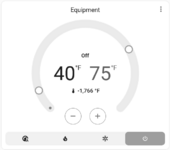
now supports dual temp settings for the equipment closet. that way i can set the heat to 40F as shown, and the cooling fan at 75F, and it will sit quietly in between. now, for the sake of argument, i could set the fans at 72F, but they would run full time in the mid season. at 75F, it will warm up, kick on the fan, cool down, kick off the fan, and so on. but i can at least play with it. unfortunately, the settings don't stay when the HA reloads for some reason... will have to plan for that.

this will run on an Arduino Mega2560, to be reliable. it will have an Arduino Ethernet shield, again, to be reliable. it will be powered by the equipment power Bus (12V DC battery/solar system), as will the security alarm. the weakest link will be if the network goes down, sadly. but that will be a wireless Ethernet bridge, that i will mount high, so it can't be tampered with easily. i will have to re-mount the house side...

i will place the project into a rack-mount enclosure case, so that it can be mounted in the equipment rack. i will have an Ethernet jack in the case, and a PSU. the wires for the solid-state-relays will exit the back of the case. perhaps with some terminals. i have two 8x terminal plugs i can use. the alarm will be in a different enclosure, so i don't need terminals for alarm in THIS case. the alarm may even just be on a rack shelf.
so, 8x outputs, and i need 8x inputs. if i start with a DTDP relay, wired like a motor reverse switch, power the outer poles, one 5V, the other Gnd. then take two wires from the center taps and route to a SPDT switch, with the 5V and Gnd taps to the SPDT outer taps, and the center tap to the arduino input. the arduino controls the DPDT relay.
 
there is a way to have switches, with only one switch and the SSR, but it requires a transistor, and two resistors for every switch, but it can be done with a central switch panel. ...or i can have a separate board in the case for the switching to take place. then i only need 3 wires. for the two signal outputs, and one return. could be as simple as XLR connectors, as i have a few. then run the wire to the switch, and i can use standard "3-way" household switches, for simplicity. or rather than the XLR, i can use the 8X screw-terminal plugs for the connections... if i get another few of those, i will have enough for 8x switches, and another pair for the SSR outputs. so i need 3x more plug connectors. or i could do something else for the SSR outputs. one of the 8x plugs, and a common ground.
whatever i do, the switch wires will need to be labeled as "Low Volt: 5Vdc", so at the switches, some screwy electrician does not fry my hardware.
but back to the transistor circuit... it is just an inverter transistor. pass the signal and anti-signal to the switch to select from. then pass the result back to the Arduino so it knows the state, and to the SSR to activate the AC circuit.

if i have a louver fan i the gable, and a open louver in the other end of the gable, i can regulate the attic temp pretty easy. i can turn the fan on so long after sunrise, and off at sunset. it could run all the time, or even setup a temp control. where it is an automatic control, i would NOT wire in the switch, and just wire it to be on with the automation control. for a fail-safe, i would put it on it's own circuit-breaker, so i can positively turn it off if needed for maintenance.

the room dust-removal system would be auto/manual control, as would the lights and air-compressor, so they can be turned on and off remotely.

in the future, when i have the remote light setup on the garage, i will want a second switch in my shop for it.

wondering about setting up a drain for the compressor. could be just a rubber hose outside somewhere. maybe out the back underneath. i will have to step up the pipe size, and add a heat-tape affair with pipe insulation... or just a garden hose a wing out the door, and pull back in when done draining.

Note to self: Air-compressor has yet to be drained since install...

Furnace will be easy to add to automation, but an A/C... not so easy. for starters, it will collect sawdust from the machine, and will need to be cleaned now and then. unfortunately, i will need a new A/C, and a big one to keep the shop cool. and i hate to cut into a new A/C... maybe just automate the furnace.
 
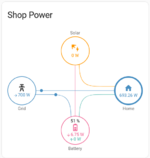
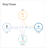
i have a Power Flow card (Power Flow Card Plus) working now, so when i get everything setup, i will know how much power is being used, and where (with limited "where").

Screenshot 2024-03-30 at 16-47-28 Overview – Home Assistant.png
Here it shows the battery charging from the grid.

Screenshot 2024-03-30 at 16-47-56 Overview – Home Assistant.png
and here it is being used by the load (equipment).

with enough sensors, i can follow the power usage, somewhat. I will be using Tamura L01Z200S05 sensors for the battery and overall load. i still need to setup the power meter KWh pulse counting. the meter does 800 pulses per KWh used. i "think" i can use this for reading how fast i am using power.
 
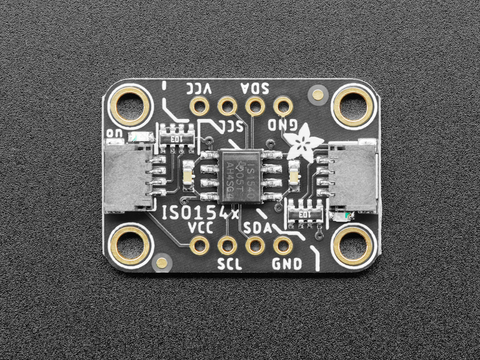
Switched to the Giga, from a Mega2560, to gain performance, and so far, i have! it is 3.3v core, but i am going to use a isolation system to help isolate power controls from the MCU. Adafruit has this:
it is a bi-directional I2C isolation board. in theory, it is like a opto-isolator, but non-optical (so not much like it...), but it does have 2.5KV isolation.
input and output will now be off-loaded to I2C devices, like a MCP23017 Relay board for output, a MCP23017 board for input, giving 16 I/O channels, though 11 switches, as the HVAC and equipment temp control also use relays. they use 5 relays, at the end of the board. i also noticed the relays are numbered wrong on the board. 0 to 15 should be 1 to 16, but is 9 to 16 and then 1 to 8.

i may have to find an enclosure that will fit the new system... it has expanded a bit...
 
perhaps as an enclosure, i can use the big ATX case. it is fit and ready for the PSU, and if i use a 3v3 to 5v I2C module rather than the isolation module, i should be fine to run everything in the same enclosure, with exception to the SSR modules for AC power. those can be in the rack-mount enclosure case. so all i need is enough connectors for the remote switch, unless i do away with that, of course. then i could have much less connections. i could have an override set of switches, just in case. wire the DC ATX PSU for full-time ON status, and if i get a failure, throw the override, and use the wall switch. could even be a single switch, maybe... no it would have to be a heavy switch for that. maybe a second set of breakers for each circuit... no, too sketchy... i just won't use an override, except for the lights. use a 3-way switch, wire the common to the lights, and one way to power, and the other way to power through the SSR case. i may even use my junction enclosure for the SSR case, as it would be safer. then i can run power inside it as needed. i need some Euro-style terminal bars to transition the wire connections safely and securely.

so the relay board will only switch low-volt, low-current devices, like HVAC thermostat and SSR low-side power. and i can leave circuit detection as is, so as too disable the external switching sensing. i just won't be able to remote control an override.

i can use some I2C temperature/humidity sensors, rather than the DHT ones i have. then i can hang one from the ceiling for room temp HVAC sensing, and use the Sparkfun Ethernet cable I2C extender. i could then use that for my fire alarm sensor, set for around 110F to 120F. same for the equipment cabinet sensor... would be nice to know if it got too hot in there.
 
it could be possible to setup a remote reset for the HA MQTT controller. i could setup a output on the Konnected Alarm panel, that seems to be reliable, and have it drive a optoisolator that pulls a reset on the controller Arduino. i do rely on the HVAC variables for the fire alarm system, so it would be a good idea.

also, i need a good enclosure for my Konnected Alarm. perhaps i could either use the RS alarm enclosure, though i hate to gut a working alarm, it would work. and there would be room for a battery backup, in the future. really, if the DC supply i feed it stays up enough, it will be just fine. a small UPS would be better though, but would not fit in the enclosure.
 
Back
Top