Notice: This write-up was intended to be team informational. this is an Extremely Experimental version of DCC-EX Command Station!
Required Libraries:
 github.com
Added config options:
Enables the use of the Adafruit WiFiNINA shield. (do not also enable Giga WiFi!)
 www.adafruit.com
MUST use the Adafruit library, or it will not work.
www.adafruit.com
MUST use the Adafruit library, or it will not work.
The Arduino IDE WILL try to overwrite this during a library update. DON'T let it! it will not work with the Arduino version of the library.
This will allow up to 9 client connections, but will list client connections that are not connected (they remove cleanly on client exit). working through if this is a bug or not...
Enables the use of the onboard Giga WiFi. (do not also enable WiFiNINA!)
Allows up to 3 clients connected (like JMRI + Engine Driver + second Engine Driver, for example).
seems stable, though.
enables the use of a Sparkfun External EEPROM, connected via I2C pins 20 and 21 (will crash if you try to use the wrong I2C pins, as the I2C ports on the Giga are NOT all connected together like the Mega 2560).
WiFi Notes:
if neither WiFiNINA or Giga WiFi are enabled, the CS will default to an ESP8266 WiFi connection.
if you wish to use other than the ESP8266 WiFi, you would need to use either the Giga WiFi config option, or the WiFiNINA config option, listed above.
for all three,
must be enabled, along with the rest of the WiFi config settings.
The On-board Giga WiFi requires an antenna to be attached to the uFL connector. a new, genuine Arduino Giga R1 WiFi will come with a basic antenna that works.
Motor Driver Notes:
I have tested with a Standard Motor Shield, and a DCC-EX EX8874 shield. both in standard single-shield (only one driver at a time) stack.
the Giga can support, at this time, 8 DCC signals (one being Main or Prog), and DC. but requires some very clever stacking, or off-stack wiring. pins 2 to 13 can be used for signal or brake pins, as they support PWM. with power pins on pins 22 to 27, and fault pins only seem to work on pins 22 through 29, if not already used.
Note: if using WiFiNINA shield, pins 10, 7, 5, and 4 can not be used for PWM or DCC. they are used by the WiFiNINA shield.
here is a sample stacked driver config for in the config.h file:
this is what i have on my development CS for testing. it allows for 4 off-stack wired EX8874 shields (though i have one in my possession, it is just for devel). the first group, tracks A and B are the Main and Prog support DCC or DC (just for devel).
only analog pins A0 to A7 can be used for current sensing pins. use of other pins may crash the Giga, or at the very least cause unexpected results.
Giga Notes:
Free memory is a very large number. the actual number would not fit in the variable size allowed, so i had to divide the number by 1000 to get it to fit, so the lower 3 digits are lost. i have not currently seen a use case where this is an issue.
my Giga shows up as COM12 or COM13, depending on it's "mood". if upload fails on COM12, change to COM13 and try again. it is annoying, but i don't know the cause of it.
if the Giga crashes (flashing red LED), try a reset. if it instantly crashes again, you will need to double-click the reset to upload again with different config options.
Serial objects are not named like on the Mega 2560.
Serial = USB serial
Serial1 = serial on pins 0 and 1.
Serial2 = serial on pins 18 and 19.
Serial3 = serial on pins 16 and 17.
Serial4 = serial on pins 14 and 15.
as mentioned somewhere above, I2C on pins 20 and 21 MUST be the I2C pins used. all I2C pins are NOT tied together.
SPI port on the ICSP headers are the ones to use. they are not connected to the port on pins 11, 12, and 13.
MOST important! the Giga is a 3.3v board! DO NOT use 5v on the digital or analog pins! it will burn the Giga!
Required Libraries:
GitHub - arduino-libraries/Arduino_AdvancedAnalog: Advanced Analog Library
Advanced Analog Library. Contribute to arduino-libraries/Arduino_AdvancedAnalog development by creating an account on GitHub.
github.com
Added config options:
C++:
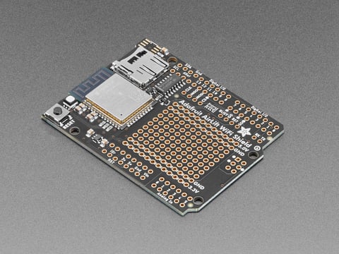
#define WIFI_NINA trueAdafruit AirLift Shield - ESP32 WiFi Co-Processor
Give your Arduino project a lift with the Adafruit AirLift Shield - a shield that lets you use the powerful ESP32 as a WiFi co-processor. You probably have your favorite Arduino-compatible ...
www.adafruit.com
The Arduino IDE WILL try to overwrite this during a library update. DON'T let it! it will not work with the Arduino version of the library.
This will allow up to 9 client connections, but will list client connections that are not connected (they remove cleanly on client exit). working through if this is a bug or not...
C++:
#define GIGA_WIFI trueAllows up to 3 clients connected (like JMRI + Engine Driver + second Engine Driver, for example).
seems stable, though.
C++:
#define GIGA_EXT_EEPROMWiFi Notes:
if neither WiFiNINA or Giga WiFi are enabled, the CS will default to an ESP8266 WiFi connection.
if you wish to use other than the ESP8266 WiFi, you would need to use either the Giga WiFi config option, or the WiFiNINA config option, listed above.
for all three,
C++:
#define ENABLE_WIFI trueThe On-board Giga WiFi requires an antenna to be attached to the uFL connector. a new, genuine Arduino Giga R1 WiFi will come with a basic antenna that works.
Motor Driver Notes:
I have tested with a Standard Motor Shield, and a DCC-EX EX8874 shield. both in standard single-shield (only one driver at a time) stack.
the Giga can support, at this time, 8 DCC signals (one being Main or Prog), and DC. but requires some very clever stacking, or off-stack wiring. pins 2 to 13 can be used for signal or brake pins, as they support PWM. with power pins on pins 22 to 27, and fault pins only seem to work on pins 22 through 29, if not already used.
Note: if using WiFiNINA shield, pins 10, 7, 5, and 4 can not be used for PWM or DCC. they are used by the WiFiNINA shield.
here is a sample stacked driver config for in the config.h file:
C++:
#define STACKED_GIGAWIFI F("STACKED_GigaWiFi"),\
  new MotorDriver(3, 12, UNUSED_PIN, 9, A0, 5.08, 5000, 28), \
  new MotorDriver(11, 13, UNUSED_PIN, 8, A1, 5.08, 5000, 29), \
  new MotorDriver(22, 10, UNUSED_PIN, UNUSED_PIN, A2, 5.08, 5000, UNUSED_PIN), \
  new MotorDriver(23, 7, UNUSED_PIN, UNUSED_PIN, A3, 5.08, 5000, UNUSED_PIN), \
  new MotorDriver(24, 6, UNUSED_PIN, UNUSED_PIN, A4, 5.08, 5000, UNUSED_PIN), \
  new MotorDriver(25, 5, UNUSED_PIN, UNUSED_PIN, A5, 5.08, 5000, UNUSED_PIN), \
  new MotorDriver(26, 4, UNUSED_PIN, UNUSED_PIN, A6, 5.08, 5000, UNUSED_PIN), \
new MotorDriver(27, 2, UNUSED_PIN, UNUSED_PIN, A7, 5.08, 5000, UNUSED_PIN)only analog pins A0 to A7 can be used for current sensing pins. use of other pins may crash the Giga, or at the very least cause unexpected results.
Giga Notes:
Free memory is a very large number. the actual number would not fit in the variable size allowed, so i had to divide the number by 1000 to get it to fit, so the lower 3 digits are lost. i have not currently seen a use case where this is an issue.
my Giga shows up as COM12 or COM13, depending on it's "mood". if upload fails on COM12, change to COM13 and try again. it is annoying, but i don't know the cause of it.
if the Giga crashes (flashing red LED), try a reset. if it instantly crashes again, you will need to double-click the reset to upload again with different config options.
Serial objects are not named like on the Mega 2560.
Serial = USB serial
Serial1 = serial on pins 0 and 1.
Serial2 = serial on pins 18 and 19.
Serial3 = serial on pins 16 and 17.
Serial4 = serial on pins 14 and 15.
as mentioned somewhere above, I2C on pins 20 and 21 MUST be the I2C pins used. all I2C pins are NOT tied together.
SPI port on the ICSP headers are the ones to use. they are not connected to the port on pins 11, 12, and 13.
MOST important! the Giga is a 3.3v board! DO NOT use 5v on the digital or analog pins! it will burn the Giga!